Pid Regulyator Na Arduino
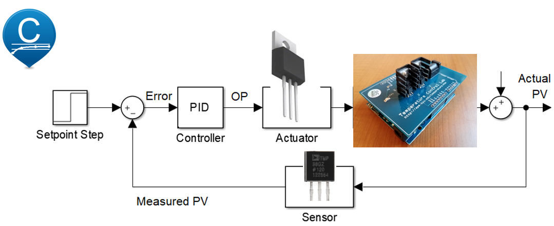
PID Definitions: The Proportional/Integral/Derivative controller or PID controller or just PID, is a proccess' control techinics that join Proportional integral and Derivative actions, thus causing the error signal is minimized by proportional action, integral action and cleared by a speed obtained with the preemptive derivative action. It is based on mathematical modeling of the response of a loop process to be controlled. In practice the PID controllers are found inside electronic controllers called 'single-loop', often with microprocessors, and also through software on programmable logic controllers (PLC) and other control equipment. In this project, we will simulate a brightness control with Arduino.
The Arduino will be running the PID library which can be found at: In addition to the PID library for Arduino, will also need the PID Front End for processing, which is a GUI in order to configure the control parameters, such as P, I, D, Set Point and ways of working, etc..; performing a user-friendly interface with Arduino. You can also download the PID_FrontEnd from the link above. As we will work with Arduino and Processing, we need to have the Arduino's IDE and Processing 1.0.1 2.0b8 installed in our computer. To the Processing software, run properly with PID_FrontEnd, we also need the library 'ContorlP5' for Processing installed in our computer. You can Download the library 'ControlP5' directly from the related link below: For details on PID control processes, I advise you to visiting the PID_V1 Library's creator website. Also access the 'Control Guru' website for more details about automation and control. Details about 'Control Systems' can be found in the website.
If any recording signifies the tenuous state of thug rap in 2010, it's Lloyd Banks' sequel to his 2004 hit The Hunger For More. But after 'Start It Up,' a furious cipher session with Kanye West, Fabolous, Swizz Beatz and Ryan Leslie, Lloyd backloads H.F.M. Hunger for more 2 review. They're not his specialty -- his mentor, 50 Cent, is much better at them -- and they weigh down this partially successful comeback album. 2 with bland R&B collaborations in an attempt to crack urban radio.
Apr 14, 2018 - There's also an LCD display and a FET to control the heater. The idea behind a PID controller is that you measure the difference between the current temperature and the desired temperature known as the setpoint. The proportional gain tells you how much output occurs due to that difference. Jump to Basic Temperature Control - /* AutoPID BasicTempControl Example Sketch This. As input, potentiometer as setpoint, drives an analog output.
Let's go now turn to the constructive aspects of our project: We will do two tests, one with the simulated environment by a dark tube (this environment will not allow interference from outside), and another test with the open environment, where we can interfere externally and thus, verify the system response. Test - 1 The environment is simulated by a dark tube (black). At one end of the tube, we will have a white LED with high-brightness (it will be used to illuminate the environment). At the other end of the tube, we will have a LDR (the LDR will be used to manage the amount of light in the environment, it will be our system's feed back). The connection with the Arduino is very simple: The pin D3 (digital 3) of the Arduino will be used as output and is connected to the LED's anode. The LED has a resistor of 220 Ohms in series with the anode (for the LED's polarization); the LED's cathode is directly connected to GND. The pin A0 (analog 0) of the Arduino will be connected to the LDR and used as analog input.
The LDR has one leg connected directly to the +5 V supply, and the another leg of the LDR is connected to a pull-down resistor value of 10K (the resistor will be connected in series with the LDR and connected to the GND. At the intersection of the LDR + resistor we will have the output signal of the light sensor that will be connected to the Arduino's pin A0. Look at the pictures to know how to do the circuit interconnection of sensors and actuators with Arduino, the circuit was designed with Fritzing. Test - 2 Now the system may suffer external actions which are called disturbances such as shading or excessive light in the sensoror in the environment or even blocking the sensor. The disturbances are automatically controlled by the Arduino_PID, ie: When we have a decrease of the incident light on the LDR (simulated by a shadow on LDR), the system will automatically increase the brightness of the LED trying to maintaining a constant ambient lighting.